
General Information
Application
- Circular VAV terminal units for use in ventilation and air conditioning systems
- VAV terminal units made from plastic, suitable for contaminated air
- For controlling, restricting or shutting off airflows, preferably extract air flows
- Closed-loop volume flow control using an external power supply
- For variable or constant volume flow systems
- Shut-off by means of switching (by others)
- Can also be used for duct or room pressure control with suitable control components
Special features
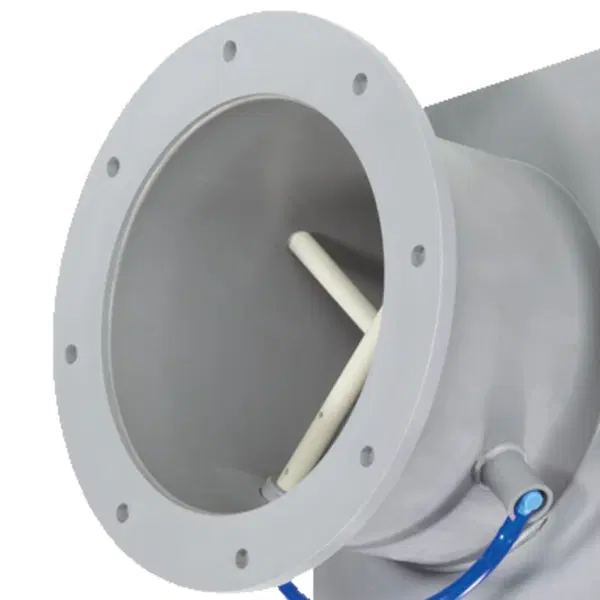
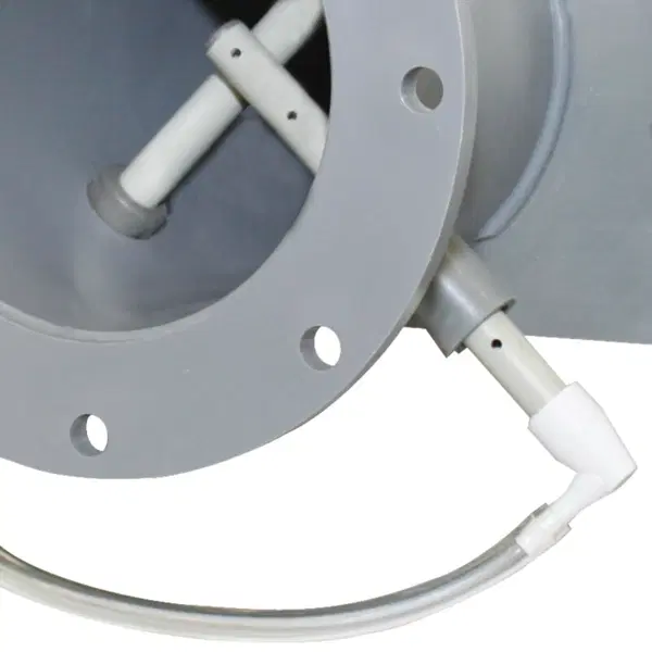
- Slide-out integral effective pressure sensor with 0.1 in measuring holes (resistant to contamination)
- Factory set-up or programming and aerodynamic function testing
- Parameters can also later be set on the control component; an additional adjustment device may be necessary
Nominal sizes
- 5, 6, 8, 10, 12, 16
Variants
- TVRK: VAV terminal unit
- TVRK-FL: VAV terminal unit with flanges on both ends
Parts and characteristics
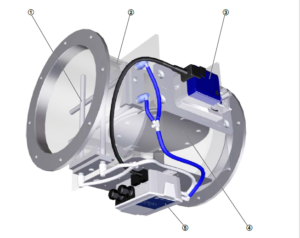
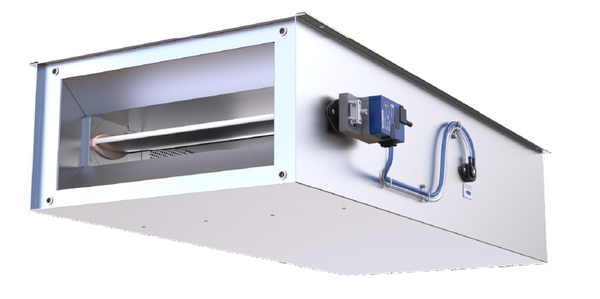
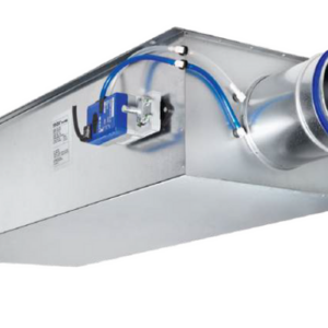
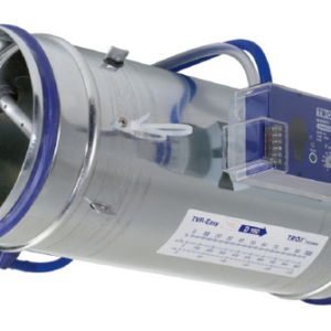
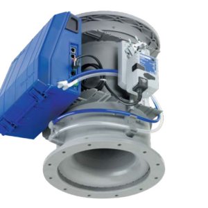
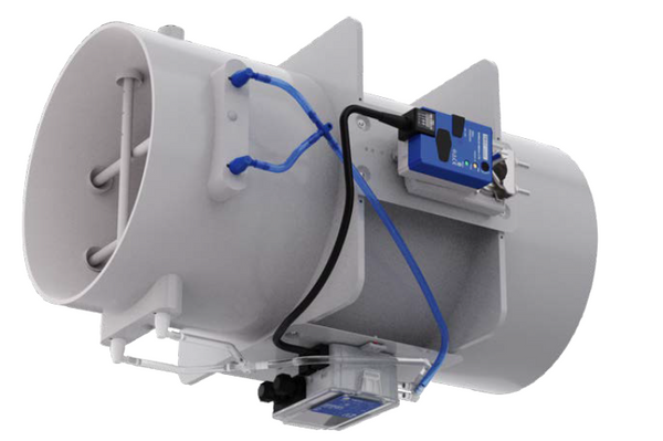
- Ready-to-commission unit which consists of mechanical parts and control components.
- Averaging effective pressure sensor for volume flow rate measurement; can be removed for cleaning
- Damper blade
- Factory mounted control components complete with wiring and tubing
- Aerodynamic functional testing on a special test rig before shipping of each unit
- Set-up data is given on a label affixed to the unit
- High control accuracy (even with upstream bend R = 1D)
Attachments
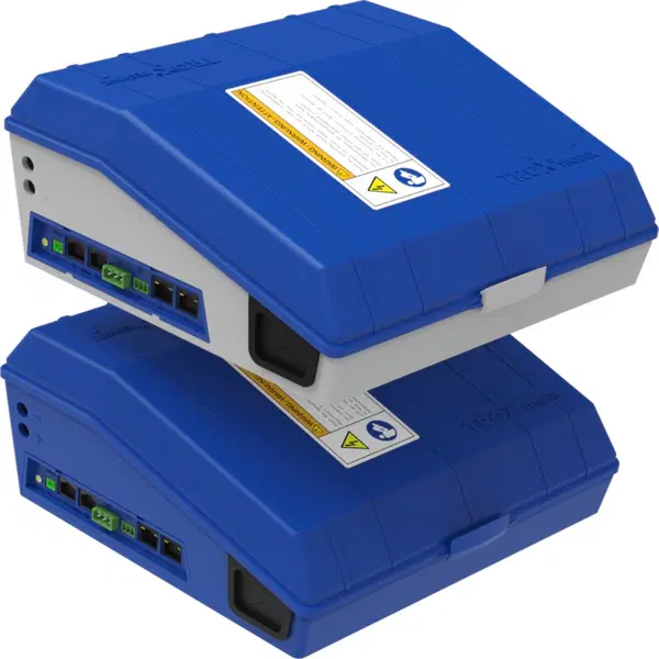
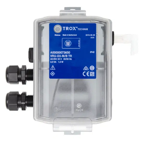
- Universal controller: controller, effective pressure transducer, and actuators for special applications
- LABCONTROL: control components for air management systems
Accessories
- Matching flanges for both ends, including seals
Useful additions
- Plastic secondary silencer Type CAK for demanding acoustic requirements
Construction features
- Circular casing
- Spigot suitable for ducts according to DIN 8077
- Both spigots with the same diameter
- Position of the damper blade indicated externally at shaft extension
Material and surfaces
- Casing and damper blade made of flame-resistant polypropylene (PPs)
- Effective pressure sensor and plain bearings made of polypropylene (PP)
- Damper blade seal made of chloroprene rubber (CR)
- Stainless steel shaft, material no. 14104
Standards and guidelines
Fulfils the hygiene requirements of
- EN 16798, Part 3
- VDI 6022, Sheet 1
- DIN 1946, Part 4
- For other applicable standards and guidelines refer to the hygiene certificate
Casing leakage
- EN 1751, Class C
Closed blade air leakage
- EN 1751, Class 3
- Meets the general requirements of DIN 1946, part 4, with regard to the acceptable closed blade air leakage
Maintenance
- Maintenance-free as construction and materials are not subject to wear
- Zero point correction of the static effective pressure transducer should be carried out once per year (recommendation)
Disclosure of Chemicals
- RoHS EU Directive 2011/65/EU (RoHS)
- This product or single variants comply with EU Directive 2011/65/EU (RoHS) on the restriction of the use of certain hazardous substances in electrical and electronic equipment. For more information, please refer to our Environmental Product Declarations
- REACH 1907/2006 (EC Regulation REACH)
- This product or single variants comply with the provisions of EC Regulation No. 1907/2006, also known as REACH (Registration, Evaluation, Authorisation and Restriction of Chemicals). For more information, please refer to our Environmental Product Declarations