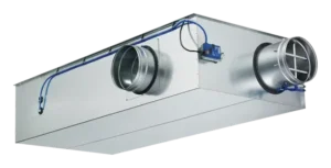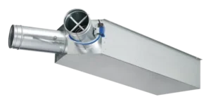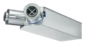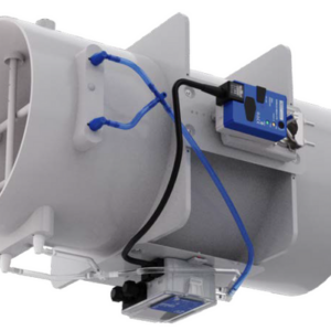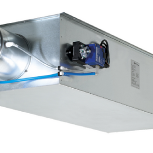
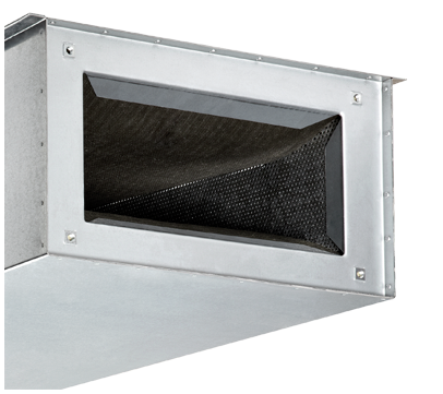

TROX TVM – VAV for Dual Duct Systems

Call for Price

For dual duct systems

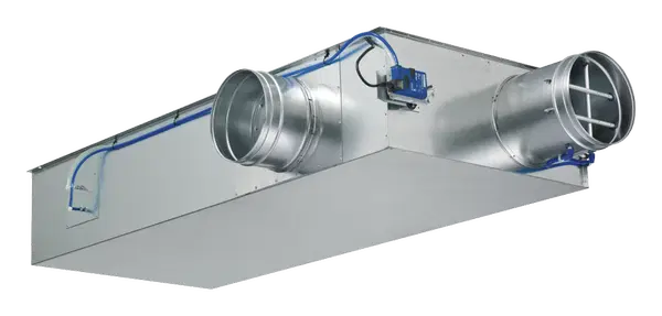
VAV dual duct terminal units for dual duct systems with variable volume flows in buildings with demanding acoustic requirements

  • Individual temperature control for each room or zone
  • Highly effective integral attenuator
  • Electronic control components for various applications
  • Closed blade air leakage to EN 1751, up to class 4
  • Casing leakage to EN 1751, Class B


Optional equipment and accessories

  • Acoustic cladding for the reduction of case-radiated noise
  • Secondary silencer Type TS for the reduction of air-regenerated noise


SKU: TVM Category: Tag:

General Information

Application

  • VAV dual duct terminal unit for use in ventilation and air conditioning systems
  • Supply air control in dual-duct volume flow systems
  • Closed-loop volume flow control using an external power supply
  • For maximum acoustic and thermal comfort
  • Demand-based mixing of cold and warm air
  • Shut-off by means of switching (by others)


Special features

  • Integral effective pressure sensor with 0.1 in measuring holes (resistant to dust and pollution)
  • Integral attenuator with at least 26 dB insertion loss at 250 Hz
  • Factory set-up or programming and aerodynamic function testing
  • Volume flow rate can later be measured and adjusted on site; additional adjustment device may be necessary
  • Inspection access according to VDI 6022


Nominal sizes

  • TVM-S: 5, 6, 8
  • TVM: 5, 6, 8, 10, 12, 16


Variants

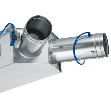
  • TVM-S Dual duct unit, 60° spigot arrangement
  • TVM-S-D Dual duct unit with acoustic cladding, 60° spigot arrangement
  • TVM: Dual duct unit, 90° spigot arrangement
  • TVM-D: Dual duct unit with acoustic cladding, 90° spigot arrangement
  • Units with acoustic cladding and/or secondary silencer Type TS for very demanding acoustic requirements
  • Acoustic cladding cannot be retrofitted


Parts and characteristics

  • Ready-to-commission unit which consists of mechanical parts and control components
  • Averaging effective pressure sensors for volume flow rate measurement, one in the cold air flow and in the total air flow respectively
  • Damper blade
  • Integral attenuator
  • Inspection access
  • Factory-mounted control components complete with wiring and tubing
  • Aerodynamic functional testing on a special test rig before shipping of each unit
  • Set-up data is given on a label affixed to the unit
  • High control accuracy (even with upstream bend R = 1D)

Attachments

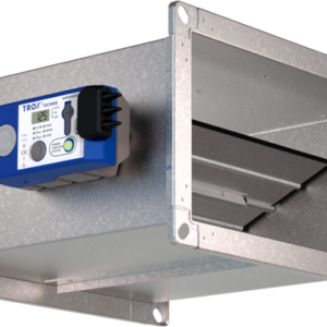
  • Compact controller: Compact unit consisting of controller with potentiometers, effective pressure transducer and actuator


Accessories

  • Double lip seals (factory-fitted)


Useful additions

  • Secondary silencer Type TS


Construction features

  • Rectangular casing
  • Spigot on the fan end suitable for circular ducts to EN 1506 or EN 13180
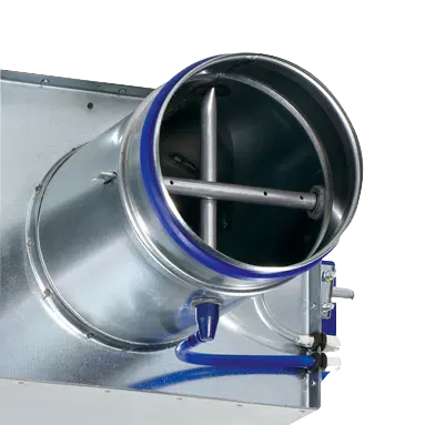
  • Spigot with groove for double lip seal
  • Connection on the room end suitable for ducts
  • Baffle plate is fitted after the damper blade for optimum aerodynamic performance
  • Position of the damper blade indicated externally at shaft extension
  • Thermal and acoustic insulation (lining)


Materials and surfaces

  • Casing and damper blade made of galvanised sheet steel
  • Damper blade seal made of TPE plastic
  • Lining is mineral wool
  • Effective pressure sensor made of aluminium
  • Plastic plain bearings
  • Shaft and linkage made of galvanised steel

Variant with acoustic cladding (-D)

  • Acoustic cladding made of galvanised sheet steel
  • Lining is mineral wool
  • Rubber elements for the insulation of structure-borne noise

Mineral wool

  • To EN 13501, fire rating class A1, non-combustible
  • RAL quality mark RAL-GZ 388
  • Non-hazardous to health thanks to being highly biosoluble in accordance with the Ordinance on Hazardous Substances and Note Q of the European Directive (EC) No. 1272/2008
  • Faced with glass fibre fabric as a protection against erosion from airflow velocities of up to 20 m/s
  • Inert to fungal and bacterial growth


Standards and guidelines

Fulfils the hygiene requirements of

  • EN 16798, Part 3
  • VDI 6022
  • DIN 1946, Part 4
  • Further standards, guidelines in accordance with hygiene certificate

Casing leakage

  • EN 1751, Class B

Closed blade leakage
Nominal sizes 5 and 6

  • EN 1751, Class 3
  • Fulfilment of the general requirements of DIN 1946, Part 4, with regard to the acceptable closed blade air leakage

Nominal sizes 8 to 16

  • EN 1751, Class 4
  • Fulfilment of the increased requirements of DIN 1946, Part 4, with regard to the acceptable closed blade air leakage


Maintenance

  • Maintenance-free as construction and materials are not subject to wear
Function

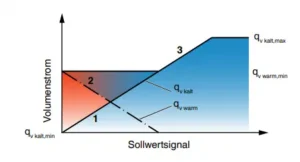
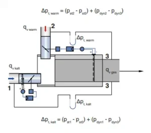
The VAV terminal unit is fitted with two effective pressure sensors for measuring the volume flow rates, one in the cold air flow and one in the total air flow. The control components (attachments) include two effective pressure transducers that transform the effective pressure into an electric signal, two controllers, and two actuators; as Compact controller or with individual components. In most cases, the setpoint value for the dual duct terminal unit comes from a room temperature controller. The room temperature controller administers the cold air volume flow controller and indicates the setpoint value for the cold air flow rate between 0 and a maximum volume flow qᵥmax. The controller compares the actual value with the setpoint value and alters the control signal of the damper actuator if there is a difference between the two values. The warm/overall


controller is set to the minimum volume flow rate qᵥmin and controls the damper blade in the heat duct. As a consequence, a corresponding proportion of warm air is added. As the demand for cooling increases, the warm air damper blade closes such that eventually only cold air flows. An integral attenuator reduces the noise that is created by the restriction of the airflow. The airflow velocity at the room end is, due to the larger rectangular cross section, about half the velocity in the circular duct.


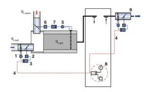
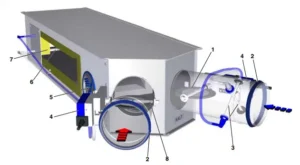
Schematic Illustration of the TVM-S

1 Damper blade for qv,cold

2 Double lip seal

3 Effective pressure sensor for qv,cold

4 Control components, e. g. a Compact controller

5 Inspection access

6 Effective pressure sensor for qv,tot

7 Noise insulation

8 Damper blade for qv,warm

Specification Text

Specification text

Rectangular VAV dual duct terminal units for dual duct systems with variable and constant volume flows, available in 6 nominal sizes. Connecting spigots for warm and cold air arranged at an angle of 90°. Up to nominal size 8, an angle of 60° is also possible and is therefore ideal for the refurbishment of older systems with dual duct units. High control accuracy (even with upstream bend R = 1D). Ready-to-commission unit which consists of the mechanical parts and the electronic control components. Each unit contains two averaging effective pressure sensors for volume flow rate measurement, one in the cold air flow and one in the total air flow, two damper blades, and an integral sound attenuator. Factory-mounted control components complete with wiring and tubing. Effective pressure sensor with 0.1 in measuring holes, hence resistant to contamination. Spigot on the fan end with groove for double lip seal, suitable for ducts according to EN 1506 or EN 13180. Room end suitable for the connection of flanges. Two baffle plates, one fitted after each damper blade for optimum acoustic and aerodynamic performance. Casing with acoustic and thermal insulation. Position of the damper blade can be seen from the outside at the shaft extension. Closed blade air leakage to EN 1751, class 4 (nominal sizes 5 and 6, class 3). Casing leakage according to EN 1751, class B. Meets the hygiene requirements of VDI 6022, EN 16798, Part 3, VDI 3803 as well as  DIN 1946 Part 4.

Special features

  • Integral effective pressure sensor with 0.1 in measuring holes (resistant to dust and pollution)
  • Integral attenuator with at least 26 dB insertion loss at 250 Hz
  • Factory set-up or programming and aerodynamic function testing
  • Volume flow rate can later be measured and adjusted on site; additional adjustment device may be necessary
  • Inspection access according to VDI 6022

Materials and surfaces

  • Casing and damper blade made of galvanised sheet steel
  • Damper blade seal made of TPE plastic
  • Lining is mineral wool
  • Aluminium sensor tubes
  • Plastic plain bearings
  • Shaft and casing made of galvanised steel

Mineral wool:

  • To EN 13501, fire rating class A1, non-combustible
  • RAL quality mark RAL-GZ 388
  • Non-hazardous to health thanks to being highly biosoluble in accordance with the Ordinance on Hazardous Substances and Note Q of the European Directive (EC) No. 1272/2008
  • Faced with glass fibre fabric as protection against erosion through airflow velocities of up to 3937 fpm
  • Inert to fungal and bacterial growth

Connection

  • Spigot with groove for double lip seal, suitable for ducts according to EN 1506 or EN 13180
  • Room end suitable for the connection of flanges


Technical data

  • Nominal sizes: 5 to 16 in
  • Volume flow rate range: 123.6 – 4468.9 cfm
  • Volume flow rate control range: approx. 30 – 100 % of the nominal volume flow rate
  • Minimum differential pressure: up to 0.81 in WG (without secondary silencer TS)
  • Maximum differential pressure: 4.02 in WG


Specification text for attachment
Variable volume flow control with electronic Compact controller to switch an external control signal and an actual value signal for integration into the central BMS.

  • Supply voltage 24 V AC/DC
  • Signal voltages 0 – 10 V DC or 2 – 10 V DC
  • Possible override controls with external, volt-free switches: CLOSE, OPEN, qᵥmin and qᵥmax
  • Volume flow rate control range: approx. 30 – 100 % of the nominal volume flow rate

Variants

Material

Standard construction

Order code detail Part Material
Casing Galvanised sheet steel
Effective pressure sensor (cold) Aluminium tube
Effective pressure sensor (total) Aluminium
Damper blade Galvanised sheet steel
Damper blade seal Thermoplastic elastomer (TPE)
Shaft and linkage Galvanised steel
Plain bearings Thermoplastic elastomer (TPE)

With acoustic cladding (optional)

Order code detail Part Material
D Lining Mineral wool to EN 13501, fire rating class A1, non-combustible
Acoustic cladding casing Galvanised sheet steel
Insulation of structure-borne noise Polyethylene, PE

Option double lip seal

Order code detail Part Material
D2 Double lip seal Rubber, EPDM


VAV Dual Duct Terminal Unit, Variant TVM

  • VAV terminal unit for the control of variable supply air volume flows
  • Connecting spigots for warm and cold air arranged at an angle of 90°

Product Details

Installation and commissioning

  • Horizontal (return edges of the casing with suspension holes at the top) and vertical installation orientation
  • Spigots for warm and cold air arranged at an angle of 60° (TVM-S) or 90° (TVM)
  • Return edges of the casing with drilled holes suitable for threaded rods


Upstream conditions

The volume flow rate accuracy Δqᵥ applies to a straight upstream section of the duct. Bends, junctions or a narrowing or widening of the duct cause turbulence that may affect measurement. Duct connections, e.g. branches off the main duct, must comply with EN 1505. Some installation situations require straight duct sections upstream. The upstream conditions apply primarily to the duct connection at the cold air spigot. Since the hot air spigot does not contain a sensor, the upstream section here has no effect on the volume flow rate accuracy; however, unfavourable upstream sections can also lead to increased sound pressure levels.


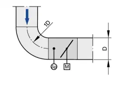
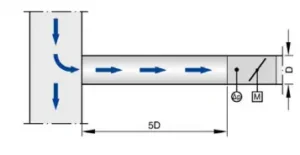
Bend

A bend with a centre line curvature radius of at least 1D – without an additional straight duct section upstream of the VAV terminal unit – has only a negligible effect on the volume flow rate accuracy.

Downloads

TVM Declaration of Conformity or Declaration of Incorporation

TVM Declaration of Hygiene Conformity

TVM Environmental Product Declaration

TVM Manufacturer’s Statement Concerning Statistical Leakage Tests

Replacing GUAC Actuators Installation Instructions