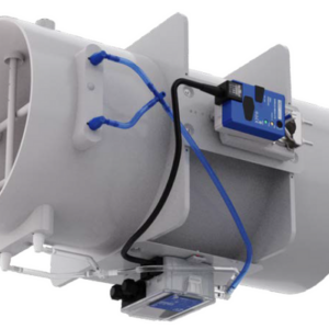
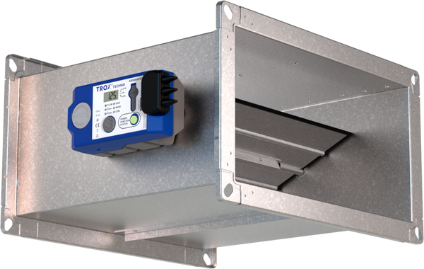

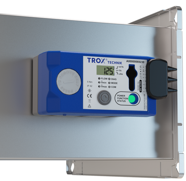


General Information
Application
- Square VAV terminal units for use in ventilation and air conditioning systems (AHUs)
- For almost all tasks when controlling, restricting, or shutting off supply and extract air flows
- Also for unfavourable upstream conditions at low air velocities
- Closed-loop volume flow control using an external power supply
- For variable or constant volume flow systems
- Shut-off by override control (by the client)
Special characteristics
- High differential pressure signal with small angle of attack
- Factory set-up or programming and aerodynamic function testing
- Volume flow rate can be measured and subsequently adjusted. Additional adjustment tool may be required (depending on the variant of the control component)
- Tubeless differential pressure measurement via damper blade
- Differential pressure transmission through differential pressure duct in axis
- Any airflow direction if dynamic transducer is used
- Any installation orientation also with static transducer
- Suitable for air velocities from 157 – 1575 fpm
- Compact dimensions for use in confined ceiling areas
Nominal sizes
- 8 × 4, 12 × 4
- 8 × 8, 12 × 8, 16 × 8, 20 × 8, 24 × 8
- 12 × 12, 16 × 12, 20 × 12, 24 × 12
Variants
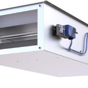
- TVE-Q: VAV terminal unit
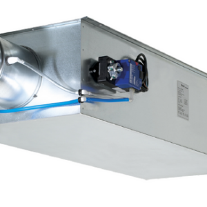
- TVE-Q-D: VAV terminal unit with acoustic cladding
- Units with acoustic cladding and/or secondary silencer Type TX for demanding acoustic requirements
Construction
- Galvanised sheet steel
- P1: Powder-coated, silver grey (RAL 7001)
Parts and characteristics
- Ready-to-commission unit which consists of mechanical parts and control components.
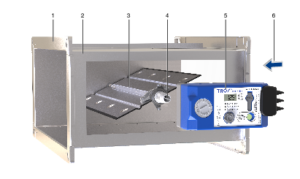
- Damper blade with integrated measuring unit
- Axis with differential pressure duct for measured value transmission
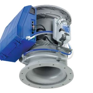
- Control component factory mounted
- Each unit is tested on a special aerodynamic test rig at the factory
- Documentation of the test rig data with a test label or a volume flow scale on the unit
- High control accuracy even in case of unfavourable upstream conditions
Attachments
- EASY controller: compact unit consisting of controller with potentiometers, differential pressure transducer and actuator
- Compact controller: compact unit consisting of controller, differential pressure transducer and actuator
- Compact controller Modbus: variant with Modbus RTU interface and disply; Plug-and-play solution in conjunction with X-AIRCONTROL room control
- Compact controller BACnet: Variant with BACnet-MS/TP interface and display; can also be converted to Modbus RTU by the customer
Useful additions
- Secondary silencer Type TX for the reduction of airregenerated noise
- Hot water heat exchanger Type WT for reheating the airflow
Construction features
- Rectangular casing
- Flanges on both ends, suitable for air duct profiles
- Position of the damper blade can be seen from the outside via position indicator
- Simple exchange of the control components possible
- Acoustic cladding cannot be retrofitted
Material and surfaces
Galvanised sheet steel variant
- Casing, damper blade made of galvanised sheet steel
- Shaft made of PA6 (H ≤ 8) or aluminium (H > 8)
- Damper blade seal and sealing plug made of EPDM
- Bearing bushes made of PBT or TPU
- Fixing (screws, rivets) galvanised steel, aluminium
Powder-coated variant (P1)
- Casing, damper blade galvanised with powder coating, RAL 7001, silver-grey
- Shaft made of PA6 (H ≤ 8) or aluminium (H > 8)
- Damper blade seal and sealing plug made of EPDM
- Bearing bushes made of PBT or TPU
- Fastening (screws, rivets) stainless steel, aluminium
Variant with acoustic cladding (-D)
- Acoustic cladding made of galvanised sheet steel
- Lining made of mineral wool
Mineral wool
- According to EN 13501, fire rating class A1, non combustible
- RAL quality mark RAL-GZ 388
- Non-hazardous to health thanks to high biosolubility according to the German Hazardous Substance Ordinance and Note Q of the European Regulation (EC) No. 1272/2008
Standards and guidelines
Meets the hygiene requirements of
- EN 16798, Part 3
- VDI 6022, Sheet 1
- DIN 1946, Part 4
- For further standards and guidelines, please refer to the hygiene certificate
Casing air leakage
- EN 1751, ATC3
Leakage airflow with the damper blade closed:
- EN1751, depending on size class 2 – 3
For further information, see “Manufacturer’s declaration on static leakage testing”
Maintenance
- Maintenance-free as construction and materials are not subject to wear and tear