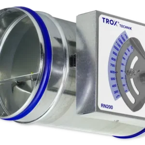
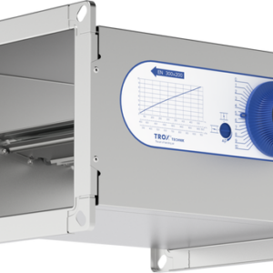
Description
Parts and characteristics
- Ready-to-commission limiter
- Damper blade with low-friction bearings
- Bellows that acts as an oscillation damper
- Leaf spring
- Lip seal
- Multi-level volume flow rate setpoint values
Construction features
- Circular casing
- Suitable for insertion into circular ducts to EN 1506 or EN 13180
- Lip seal for tight and secure fit
- Acoustically optimised damper blade with low-friction bearings and special bellows
- Different damper blade construction and volume flow rate sticker for nominal size 6
Materials and surfaces
- Casing and damper blade made of high-quality plastic, to UL 94, V0; to DIN 4102, material classification B2
- Leaf spring made of stainless steel
- Polyurethane bellows
Standards and guidelines
- Hygiene conforms to VDI 6022
Maintenance
- Maintenance-free as construction and materials are not subject to wear
Disclosure of Chemicals
- RoHS EU Directive 2011/65/EU (RoHS)
- This product or single variants comply with EU Directive 2011/65/EU (RoHS) on the restriction of the use of certain hazardous substances in electrical and electronic equipment. For more information, please refer to our Environmental Product Declarations.
- REACH 1907/2006 (EC Regulation REACH)
- This product or single variants comply with the provisions of EC Regulation No. 1907/2006, also known as REACH (Registration, Evaluation, Authorisation and Restriction of Chemicals). For more information, please refer to our Environmental Product Declarations
Function
Functional description
The volume flow limiter is a mechanical self-powered unit and works without external power supply. A damper blade with low-friction bearings is adjusted by aerodynamic forces such that the set volume flow rate is limited as a consequence.
The aerodynamic forces of the airflow create a closing torque on the damper blade. The bellows extends and increases this force while at the same time acting as an oscillation damper. The closing force is countered by a leaf spring. As the differential pressure changes, the leaf spring adjusts the position of the damper blade such that the volume flow rate is limited.
Efficient commissioning
The volume flow limiter performs the previously tedious and expensive balancing of volume flow rates in ventilation and air conditioning systems.
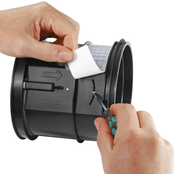
Simple handling and perfect function help to save valuable working time on site. The required volume flow rate can be set at the point of installation, then the volume flow limiter is inserted into the duct. The set volume flow rate will then be limited and maintained within close tolerances.
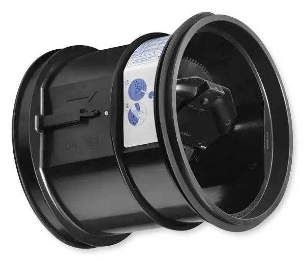
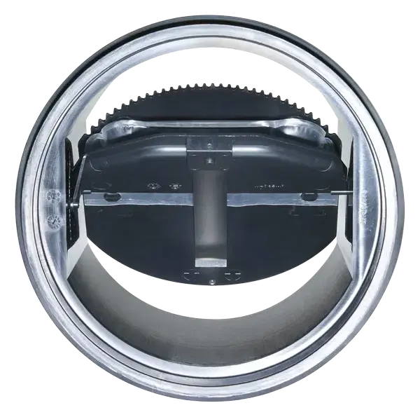
Schematic illustration of the VFL
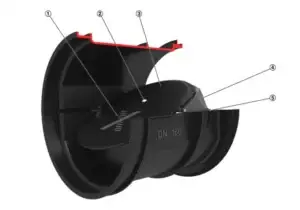
① Damper blade
② Bellows inlet
③ Bellows
④ Crossbar
⑤ Volume flow rate scale
Specification Text
Circular volume flow limiters in 7 nominal sizes, made of high-quality plastic, to limit and control volume flows in air conditioning systems.
Ready-to-commission unit which consists of the casing with setpoint scale and the control mechanism with leaf spring and low-friction, silicone-free bellows.
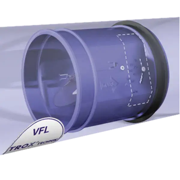
Easy insertion into circular ducts to EN 1506 or EN 13180; secure fit ensured by a lip seal.
Aerodynamically tested and factory set to a reference volume flow rate. Can be subsequently accurately adjusted within a volume flow rate range of at least 5 : 1.
Special features
- Mechanical self-powered
- Low-friction bellows
- For circular ducts
- Lip seal for tight and secure fit
- Aerodynamically tested and factory set to a reference volume flow rate
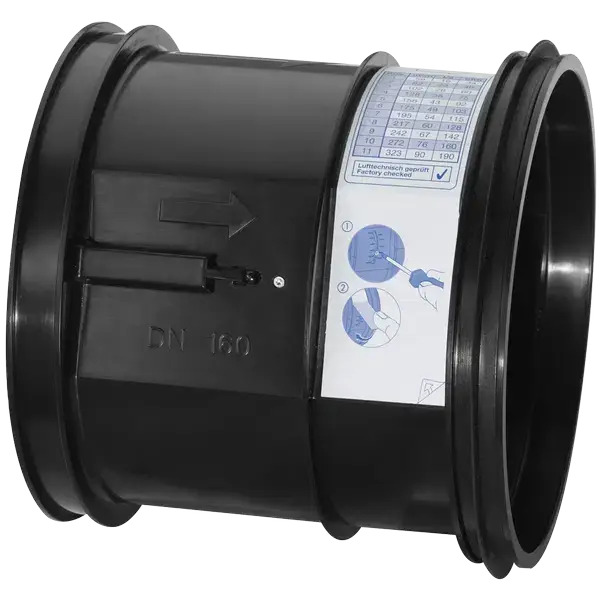
- Sticker showing volume flow rates (in l/s, m³/h and cfm) that can be set each limiter
Materials and surfaces
- Casing and damper blade made of high-quality plastic, to UL 94, V0; to DIN 4102, material classification B2
- Leaf spring made of stainless steel
- Polyurethane bellows
Technical data
- Nominal sizes: 3″ – 10″
- Volume flow rate range: 8 to 450 cfm
- Volume flow rate control range: < 20 to 100 % of the nominal volume flow rate
- Volume flow rate accuracy: approx. ± 10 % of the nominal volume flow rate
- Minimum differential pressure: 0.1 in WC
- Maximum differential pressure: 1 in WC
Life cycle assessment
A life cycle assessment is available for the product series in form of an Environmental Product Declaration (EPD) that has been checked and published by a programme holder.
Installation Details
Installation and commissioning
- Any installation orientation
- Set the required volume flow rate using a scale
- Insert the unit into the duct
- Mark the installation location
Upstream conditions
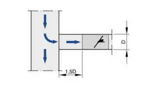
The volume flow rate accuracy ΔV applies to a straight upstream section of the duct. Bends, junctions or a narrowing or widening of the duct cause turbulence that may affect measurement. Duct connections, e.g. branches off the main duct, must comply with EN 1505. Some installation situations require straight duct sections upstream.
Free air intake only with a straight duct section of 1D upstream.
Space required for commissioning and maintenance
Sufficient space must be kept clear near any attachments to allow for commissioning and maintenance. It may be necessary to provide sufficiently sized inspection access openings.
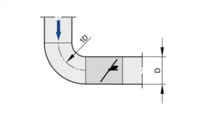
Bend
A bend with a curvature radius of at least 1D – without an additional straight duct section upstream of the volume flow limiter – has only a negligible effect on the volume flow rate accuracy.