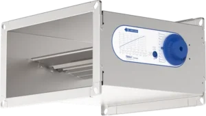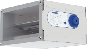
TROX EN – Rectangular Constant Volume Regulator

Call for Price

For precise control of normal to high constant volume flow rates

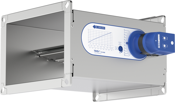
Rectangular, mechanically self-powered air terminal units for supply and extract air systems with constant air volume flows

  • Suitable for volume flow rates up to 7416 cfm
  • Volume flow rate adjustment from outside by rotary knob
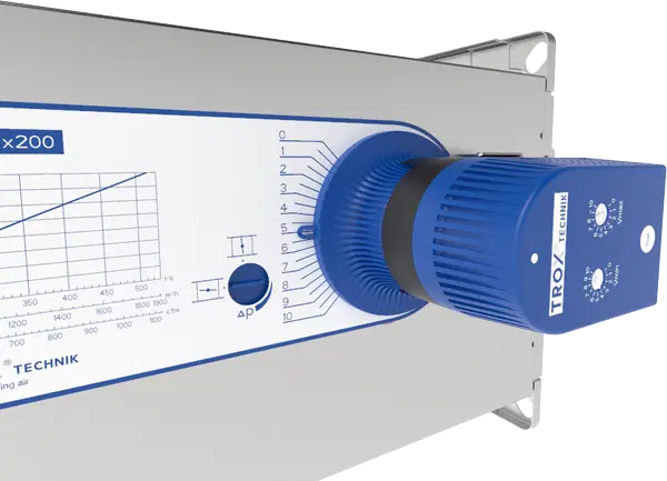
  • Easy retrofitting of an actuator for volume flow setpoint adjustment
  • High control accuracy
  • No on-site test measurements required for commissioning
  • Casing air leakage to EN 1751, class C
  • Visual display of the damper blade position for operating point optimisation


Optional equipment and accessories

  • Acoustic cladding for the reduction of case-radiated noise
  • Secondary silencer Type TX for the reduction of air-regenerated noise
  • Hot water heat exchanger Type WT for reheating the airflow
  • Actuator for setpoint value switching or steady operation


SKU: EN Category: Tag:

General Information

Application

  • Rectangular CAV terminal units for supply or extract air volume flow control in constant volume flow systems
  • Mechanical self-powered volume flow control without external power supply
  • Simplified project handling by ordering based on nominal size


Special features

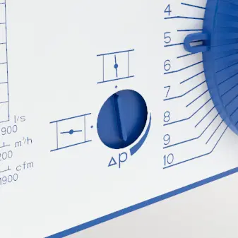
  • Setting of the volume flow setpoint from the outside by rotary knob
  • High control accuracy of the set volume flow rate
  • Correct operation even under unfavourable upstream conditions
  • Visual display of the damper blade position for operating point optimisation
  • Easy retrofitting of an actuator for volume flow setpoint adjustment


Nominal sizes

  • 19 nominal sizes from 8 × 4 – 24 × 24 in


Variants

  • EN: Air terminal units
  • EN-D: Air terminal units with acoustic cladding
  • Air terminal units with acoustic cladding and/or secondary silencer type TX for high acoustic requirements

Construction

  • Galvanised sheet steel
  • P1: Powder-coated, silver grey (RAL 7001)


Parts and characteristics

  • Air terminal unit ready for commissioning
  • Damper blade with low-friction bearings
  • Bellows for vibration damping
  • Cam plate with leaf spring
  • Rotary knob pointer and scale for adjusting the flow rate setpoint
  • Each air terminal unit is tested in the factory on a special ventilation test rig
  • Visual display of the damper blade position for operating point optimisation


Attachments

  • Min/Max actuators: Actuators for switching between minimum and maximum volume flow rate setpoint values
  • Variable actuators: actuators for variable volume flow or for switching volume flow setpoints
  • EN with actuator only up to H = 300 mm


Useful additions

  • Secondary silencer Type TX
  • Heat exchangers Type WT


Construction features

  • Rectangular casing
  • Flanges on both ends, suitable for duct connections
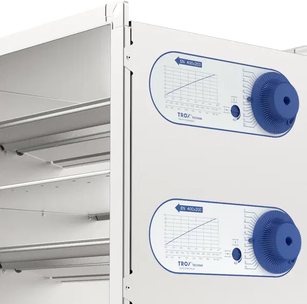
  • Air terminal units from H = 16 in as double version (2 dampers with separate setting scales)
  • Acoustic cladding cannot be retrofitted


Materials and surfaces

Galvanised sheet steel construction

  • Casing and damper blade made of galvanised sheet steel
  • Leaf spring made of stainless steel
  • Polyurethane bellows
  • Plain bearings with PTFE coating
  • Cam plate and adjusting unit made of galvanised sheet steel

Powder-coated construction (P1)

  • Casing and damper blade made of galvanised sheet steel, powder-coated
  • Leaf spring made of stainless steel
  • Polyurethane bellows
  • Plain bearings with PTFE coating
  • Cam plate and adjusting unit made of galvanised sheet steel

Variant with acoustic cladding (-D)

  • Acoustic cladding made of galvanised sheet steel
  • Rubber seal for the insulation of structure-borne noise
  • Lining made of mineral wool

Mineral wool

  • Acc. to EN 13501, fire rating class A1, non-combustible
  • RAL quality mark RAL-GZ 388
  • Non-hazardous thanks to high biosolubility according to the German Ordinance on Hazardous Substances and Note Q of the European Regulation (EC) No. 1272/2008


Standards and guidelines

Meets the hygiene requirements of

  • EN 16798, Part 3
  • VDI 6022, Sheet 1
  • DIN 1946, Part 4
  • For further standards and guidelines, please refer to the hygiene certificate

Casing air leakage

  • EN 1751, Class C


Maintenance

Maintenance-free as construction and materials are not subject to wear
Function

Functional description

The air terminal unit is a mechanical self-powered unit and works without external power supply. A damper blade with low-friction bearings is adjusted by aerodynamic forces so that the set volume flow rate is kept constant within the differential pressure range. The aerodynamic forces of the airflow create a closing torque on the damper blade. An inflating bellows amplifies this force and at the same time acts as a damping element. The closing torque is countered by a leaf spring that unrolls over a cam plate. The cam plate is adapted in such a way that the damper blade moves when the differential pressure changes. As a result, the volume flow rate remains constant within narrow tolerances.

Efficient commissioning

Using the rotary knob, the desired volume flow setpoint can be set quickly on the external scale, no prior measurement required. The advantage over conventional flow adjustment dampers is that no repeated measurements or adjustments during commissioning are required. Should the system pressure change, e.g. by opening or closing of duct sections, the flow rates in the entire system will also change if flow adjustment dampers are used; however, this is not the case with mechanical self-powered air terminal units. The air terminal unit reacts immediately and keeps the set air volume constant.


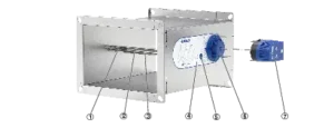
Schematic Illustration of the EN

① Damper blade

② Bellows

③ Bellows inlet

④ Scale sticker

⑤ Visual display of the damper blade position

⑥ Rotary knob

⑦ Actuator (optional)

Specification Text

Specification text

Air terminal units in rectangular design for constant air volume systems, mechanically self-powered, without external power supply, for supply or extract air, in 19 nominal sizes.

Air terminal unit ready for commissioning. Unit consists of the casing with damper blade with low friction bearings, bellows, and external cam plate with leaf spring. The air terminal units are factory adjusted and preset to a reference air volume. Sound power level measured according to DIN EN ISO 5135. Meets the hygiene requirements according to VDI 6022.

Special features

  • Setting of the volume flow setpoint from the outside by rotary knob
  • High control accuracy of the set volume flow rate
  • Correct operation even under unfavourable upstream conditions
  • Visual display of the damper blade position for operating point optimisation
  • Easy retrofitting of an actuator for volume flow setpoint adjustment


Materials and surfaces

Galvanised sheet steel construction

  • Casing and damper blade made of galvanised sheet steel
  • Leaf spring made of stainless steel
  • Polyurethane bellows
  • Plain bearings with PTFE coating
  • Cam plate and adjusting unit made of galvanised sheet steel

Powder-coated construction (P1)

  • Casing and damper blade made of galvanised sheet steel, powder-coated
  • Leaf spring made of stainless steel
  • Polyurethane bellows
  • Plain bearings with PTFE coating
  • Cam plate and adjusting unit made of galvanised sheet steel

Variant with acoustic cladding (-D)

  • Acoustic cladding made of galvanised sheet steel
  • Rubber seal for the insulation of structure-borne noise
  • Lining made of mineral wool

Mineral wool

  • Acc. to EN 13501, fire rating class A1, non-combustible
  • RAL quality mark RAL-GZ 388
  • Non-hazardous thanks to high biosolubility according to the German Ordinance on Hazardous Substances and Note Q of the European Regulation (EC) No. 1272/2008


Construction

  • Galvanised sheet steel
  • P1: Powder-coated, silver grey (RAL 7001)


Technical data

  • Nominal sizes: 8 × 4 to 24 × 24 in
  • Volume flow rate range: 82 – 7416 cfm
  • Volume flow rate control range: approx. 25 – 100 % of the nominal volume flow rate
  • Minimum differential pressure: 0.2 in WC
  • Maximum permissible differential pressure: 4 in WC
  • Casing air leakage acc. to EN 1751, class C


Life cycle assessment
A life cycle assessment is available for the product series in form of an Environmental Product Declaration (EPD) that has been checked and published by a programme holder.

Variants

  • Air terminal units for constant air volume flow control
  • Air terminal units with acoustic cladding for constant air volume flow control
  • For rooms in which the case-radiated noise of the unit is not sufficiently reduced by a suspended ceiling
  • The rectangular ducts for the room under consideration must have adequate acoustic insulation (provided by others) on the fan and room ends
  • Acoustic cladding cannot be retrofitted


EN

Product Details

Installation and commissioning

  • Installation with horizontal air flow: Do not point the operating side (setting scale, rotary knob or optional actuator) upwards
  • Setting of the volume flow setpoint from the outside by rotary knob
  • Loosen and lock the rotary knob with hexagon socket screw
  • No repeated measuring or re-adjusting required during commissioning
  • EN-D: For constructions with acoustic cladding, ducts on the room side should have cladding up to the acoustic cladding of the air terminal unit


Upstream conditions

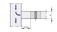
The volume flow rate accuracy Δqvapplies to a straight upstream section of the duct. Fittings such as bends, junctions, or changes in cross-section cause turbulence that can influence the volume flow accuracy. Duct connections, e.g. branches off the main duct, must comply with EN 1505. Free air intake only with 1.5B or 1.5H straight upstream length.


Space required for commissioning and maintenance

To enable commissioning and maintenance work, keep sufficient installation space clear in the area of the operating side (setting scale, rotary knob, optional attachment parts). It may be necessary to provide sufficiently sized inspection openings to make sure the attachments are easily accessible.


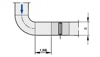
Bend, Horizontal

Between any bend and the CAV terminal unit, a straight duct section of at least 1.5B upstream length is required to achieve the stated volume flow rate accuracy Δqv .

Downloads

Retrofit Kits Product Data Sheet

EN Product Data Sheet

EN_HC_2020_06_08_DE_enpdf

EN Declaration of Conformity or Declaration of Incorporation

EN Declaration of Hygiene Conformity

EN Declaration of Incorporation

EN-D Environmental Product Declaration

EN Manufacturer’s Statement Concerning Statistical Leakage Tests

EN Retrofitting Actuators E01-E03 Installation Manual

EN Installation Manual