
TROX UL – Non-return dampers for installation into walls or rectangular ducts

Call for Price

For installation into walls or rectangular ducts

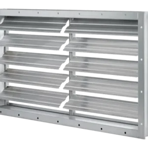
Non-return dampers prevent unwanted airflows against the intended airflow direction when the system is not in operation

  • Maximum differential pressure: 0.4 in w.g.
  • Maximum width of 63 in, maximum height of 64 in
  • Frame with fixing holes along the perimeter
  • Available in standard sizes and intermediate sizes (in increments of 0.04 in)
  • Non-return damper with formed aluminium blades for normal requirements; blades are fitted with seals


Optional equipment and accessories

  • Installation subframe
  • Powder coating, RAL CLASSIC colour


SKU: UL Category: Tag:

General Information

Application

  • Type UL non-return dampers for installation into internal walls and rectangular ducts
  • Prevention of unwanted airflows against the intended airflow direction when the system is not in operation
  • Blades close automatically when the system is shut down
  • Maximum differential pressure: 0.4 in w.g.


Special characteristics

  • Any intermediate sizes within the standard size range are available
  • operating temperature: –4 – 176 °F
  • Maximum differential pressure: 0.4 in w.g.
  • Non-return dampers are opened and closed by the airflow; no actuator is required
  • Non-return damper with formed aluminium blades for normal requirements; blades are fitted with seals for sound attenuation


Nominal sizes

  • B: 8, 16, 24, 32, 39, 47, 55, 63 in (intermediate sizes: 8 – 63 in in increments of 0.04 in)
  • H: 8, 12, 16, 20, 24, 28, 32, 40, 48, 56, 64 in (intermediate sizes: 9 – 64 in, in increments of 0.04 in)
  • Any combination of B × H


Variants

  • UL-1: Non-return damper for airflows directed towards the installation side
  • UL-2: Non-return damper for airflows directed towards the rear side (suction)


Parts and characteristics

  • Frame
  • Blades with low-friction bearings
  • Blade restrictors
  • Blade tip seals
  • Bottom travel stop (angle section)
  • Visible mullion from B = 39 in


Parts and characteristics

  • Border
  • Blades with low-friction bearings
  • Blade restrictors
  • Blade tip seals
  • Bottom travel stop (angle section)
  • Visible mullion from B = 39 in


Construction features

  • Frame, material thickness 0.07 in, with fixing holes
  • Blades, material thickness 0.04 in
  • Additional side bar with fixing holes to accommodate the blade shafts and integral blade restrictors
  • Blade restrictors prevent the blades from opening beyond a certain angle


Accessories

  • Installation subframe: Installation subframe for the fast and simple installation of mechanically self-powered dampers


Technical data

  • Nominal sizes: 8 × 8 to 63 × 64 in
  • Volume flow rate range: 233 – 13688 cfm at 492 fpm
  • Total differential pressure: 0.1 in w.g. at 294 fpm
  • Maximum differential pressure in closing direction: 0.4 in w.g.
  • Operating temperature: –4 to 176 °F
Description

Variants

  • UL-1: Non-return damper for airflows directed towards the installation side
  • UL-2: Non-return damper for airflows directed towards the rear side (suction)


Parts and characteristics

  • Border
  • Blades with low-friction bearings
  • Blade restrictors
  • Blade tip seals
  • Bottom travel stop (angle section)
  • Visible mullion from B = 39 in


Construction features

  • Frame, material thickness 0.07 in, with fixing holes
  • Blades, material thickness 0.04 in
  • Additional side bar with fixing holes to accommodate the blade shafts and integral blade restrictors
  • Blade restrictors prevent the blades from opening beyond a certain angle


Nominal sizes

  • B: 8, 16, 24, 32, 39, 47, 55, 63 in (intermediate sizes: 8 – 63 in in increments of 0.04 in)
  • H: 8, 12, 16, 20, 24, 28, 32, 40, 48, 56, 64 in (intermediate sizes: 9 – 64 in, in increments of 0.04 in)
  • Any combination of B × H

Function

Non-return dampers open and close automatically. When the system is in operation, the blades open when air flows. When the system is shut down, the blades close due to their weight. They safely prevent air from flowing against the intended airflow direction.


Schematic Illustration of UL-1

1 Frame

2 Blades (closed)

3 Mullion from B = 39 in

4 Travel stop (angle section)

5 Blades (open)

6 Blade restrictor

7 Blade tip seals

8 Side bar

Specification Text

Rectangular non-return dampers to prevent air from flowing against the intended airflow direction; for installation into internal walls and into rectangular ducts.

Ready-to-install component which consists of a border, blades with low-friction bearings, and travel stop and sealing parts.


Special characteristics

  • Any intermediate sizes within the standard size range are available
  • operating temperature: –4 – 176 °F
  • Maximum differential pressure: 0.4 in w.g.
  • Non-return dampers are opened and closed by the airflow; no actuator is required
  • Non-return damper with formed aluminium blades for normal requirements; blades are fitted with seals for sound attenuation


Accessories

  • Installation subframe: Installation subframe for the fast and simple installation of mechanically self-powered dampers

Technical data

  • Nominal sizes: 8 × 8 to 63 × 64 in
  • Volume flow rate range: 233 – 13688 cfm at 492 fpm
  • Total differential pressure: 0.09 in w.g. at 492 fpm
  • Maximum differential pressure in closing direction: 0.4 in w.g.
  • Operating temperature: -4 to 176 °F

Downloads

UL Declaration of Conformity or Declaration of Incorporation

UL Non-CE Manufacturer’s Statement