

General Information
Application
- Circular flow adjustment dampers Type VFR for the simple balancing of volume flows and pressures in air conditioning systems
- Continuous variable adjustment of the volume flow by means of a hand wheel with position indicator
- Simple retrofitting of an actuator
- Pressure dependent leakage airflow with minimal setting (setting 0)
Special characteristics
- Diagram with setting values on each flow adjustment damper
- Simple retrofitting of an actuator
Nominal sizes
- 3, 4, 5, 6, 7, 8, 9, 10
Construction
- Galvanised sheet steel
- A2: Stainless steel
Parts and characteristics
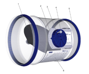
- Ready-to-install flow adjustment damper
- Hand wheel with position indicator
- Continuous variable adjustment from 0 to 10
- Diagram with setting values
- Lip seal
Attachments
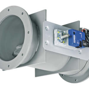
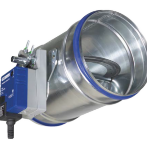
- Min/Max actuators: actuators for switching between minimum and maximum volume flow setpoints
- Modulating actuators: actuators for varying volume flow setpoints
Construction features
- Spigot with lip seal, for circular connecting ducts to EN 1506 or EN 13180
- Very good dimensional stability due to double grooves
- Damper blade with a 0.12 in circumferential gap, without a seal
Material and surfaces
- Hand wheel, damper blade and plain bearings made of plastic, flame retardant (V-0) to UL 94
Galvanised sheet steel variant
- Casing made of galvanised sheet steel
Stainless steel variant (A2)
- Casing made of stainless steel 1.4301
Standards and guidelines
- Meets the hygiene requirements of VDI 6022
- Casing air leakage according to EN 1751, class C
Maintenance
- Maintenance-free as construction and materials are not subject to wear
Disclosure of Chemicals
- RoHS EU Directive 2011/65/EU (RoHS)
- This product or single variants comply with EU Directive 2011/65/EU (RoHS) on the restriction of the use of certain hazardous substances in electrical and electronic equipment. For more information, please refer to our Environmental Product Declarations.
- REACH 1907/2006 (EC Regulation REACH)
- This product or single variants comply with the provisions of EC Regulation No. 1907/2006, also known as REACH (Registration, Evaluation, Authorisation and Restriction of Chemicals). For more information, please refer to our Environmental Product Declarations.