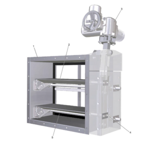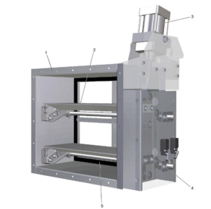
TROX NAK – For the gas-tight shut-off of ducts

Call for Price

FOR THE GAS-TIGHT SHUT-OFF OF DUCTS

Fulfils the level of ‘leak tightness’ required by KTA Guideline 3601 (German Nuclear Safety Standards Commission, KTA) and by DIN 25496 even when the power supply or compressed air supply fails

  • Compact construction and robust actuator mechanism allow for any installation orientation
  • Maximum leakage air flow of closed damper is 0.00055 cfm/ft² at a differential pressure of 8.03 in w.g.
  • Gas-tight closure, even when there is no power, due to special toggle lever principle
  • Variants with hand wheel, pneumatic actuator or electric actuator
  • Brass bearings
  • Powder-coated casing and blades
  • Maximum pressure loading of 20.07 in w.g., in closing direction
  • Available in standard sizes and many intermediate sizes


Optional equipment and accessories

  • Flange holes
  • Limit switch
  • Double acting pneumatic actuator, with optional solenoid valve
  • Electric actuator 3~ 400 V AC, 50 Hz or 1~ 230 V AC, 50 Hz


SKU: NAK Category: Tag:

General Information

Application

  • For shutting off air ducts in ventilation and air conditioning systems with the highest safety-related requirements for low leakage of the shut-off (gas-tight)
  • Fulfils the level of ‘leak tightness’ required by KTA Guideline 3601 (German Nuclear Safety Standards Commission, KTA) and by DIN 25496 even when the power supply or compressed air supply fails


Special characteristics

  • Compact construction and robust actuator mechanism allow for any installation orientation
  • With a special drive mechanism, the so-called toggle lever principle: this means that the closed shut-off damper fulfils the required tightness, even if the closing energy fails
  • Maximum leakage air flow of closed damper is 0.00055 cfm/ft² at a differential pressure of 8.03 in w.g.
  • Maximum pressure loading of 20.07 in w.g., in closing direction


Nominal sizes

  • B: 16, 24, 32, 39 in (intermediate sizes: 16 – 39 in, in increments of 0.04 in)
  • H: 11, 20, 30, 39 in
  • Any combination of B × H possible


Variants

  • NAK-H: gas-tight shut-off damper with hand wheel
  • NAK-P: gas-tight shut-off damper with pneumatic actuator
  • NAK-E: gas-tight shut-off damper with electric actuator (3~ 400 V AC, 50 Hz)
  • NAK-E1: gas-tight shut-off damper with electric actuator (1~ 230 V AC, 50 Hz)


Constructions

  • Duct connection unperforated
  • G: Flange holes on both sides


Attachments

  • Attachments: for opening and closing, and for capturing the blade end positions


Construction features

  • Casing made of welded U-channel sections, material thickness 0.12 in
  • Blades and special sealing frame, material thickness 0.08 in
  • External blade dynamics with 2 pivot points and deflection elements (toggle lever principle)
  • OPEN blades rest against the travel stops
  • CLOSED blades are pressed against the seal
  • Special sealing frame fitted with glued-in seals, welded into the casing


Material and surfaces

  • Casing made of galvanised sheet steel with RAL 7001 powder-coating
  • Blades and sealing frame made of galvanised sheet steel with RAL 7001 powder coating
  • Drive linkage, travel stops and further attachments made of galvanised steel
  • Brass bearings
  • Shafts made of stainless steel 1.4301
  • Seals made of neoprene rubber foam, temperature resistant up to 176 °F


Standards and guidelines

  • Leakage air flow of closed shut-off blade according to KTA 3601 Guideline (German Nuclear Safety Standards Commission, KTA) and DIN 25496
  • Casing air leakage to EN 1751, class C


Maintenance

  • Contamination should be removed as it may lead to corrosion
  • Lubricate friction points and bearings
  • NAK-H, NAK-E, NAK-E1: Lubricate threaded spindle
  • Lubricating intervals depend on the application: every six to twelve months or after a maximum of 2000 switching cycles
  • Use only oil or grease that is free of resins or acids.
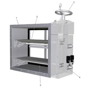
Function

Schematic Illustration of NAK-H

① Casing
② Blade
③ Rotary knob
④ Linkage (over centre locking)
⑤ Seal

Specification Text

Rectangular shut-off dampers for shutting off ducts (gas-tight).

Level of tightness required by KTA Guideline 3601 (German Nuclear Safety Standards Commission, KTA) and by DIN 25414 even when the power supply or compressed air supply fails.

Ready-to-operate unit which consists of the casing, blades and the blade mechanism (over centre locking).

Flanges on both sides, suitable for duct connection.

Suitable for duct pressures up to 20.07 in w.g.

Special characteristics

  • Compact design and robust actuator mechanism allow for any installation orientation
  • Gas-tight closure, even when there is no power, due to special over centre locking mechanism
  • Maximum closed blade leakage rate is 0.00055 cfm/ft² at a differential pressure of 8.03 in w.g.
  • Maximum pressure loading of 20.07 in w.g., in closing direction

Materials and surfaces

  • Casing made of sheet steel, material no. EN 10142-DX51D+Z150-200
  • Blades and sealing frame made of sheet steel, material no. EN 10327-DX51D+Z150-200-NAC
  • Linkage, travel stops and further attachments made of galvanised steel
  • Brass or stainless steel bearings
  • Seals made of neoprene rubber foam, temperature resistant up to 176 °F
  • Powder-coated casing and blades, grey (RAL 7001)

Construction

  • Duct connection without flange holes
  • G: Flange holes on both sides

Technical data

  • Nominal sizes: 16 × 11 to 39 × 39 in
  • Maximum differential pressure: 20.07 in w.g., in closing direction
  • Closed blade air leakage: < 0.00055 cfm/ft²