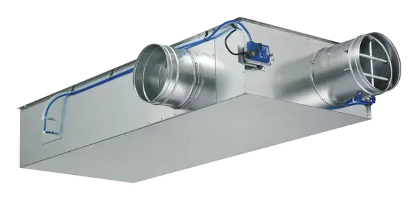
Description
FOR DUAL DUCT SYSTEMS
VAV dual duct terminal units for dual duct systems with variable volume flows in buildings with demanding acoustic requirements
- Individual temperature control for each room or zone
- Highly effective integral attenuator
- Electronic control components for various applications
- Closed blade air leakage to EN 1751, up to class 4
- Casing leakage to EN 1751, Class B
Optional equipment and accessories
- Acoustic cladding for the reduction of case-radiated noise
- Secondary silencer Type TS for the reduction of air-regenerated noise
Application
- VAV dual duct terminal unit for use in ventilation and air conditioning systems
- Supply air control in dual-duct volume flow systems
- Closed-loop volume flow control using an external power supply
- For maximum acoustic and thermal comfort
- Demand-based mixing of cold and warm air
- Shut-off by means of switching (by others)
Special features
- Integral effective pressure sensor with 3 mm measuring holes (resistant to dust and pollution)
- Integral attenuator with at least 26 dB insertion loss at 250 Hz
- Factory set-up or programming and aerodynamic function testing
- Volume flow rate can later be measured and adjusted on site; additional adjustment device may be necessary
- Inspection access according to VDI 6022
Nominal sizes
- TVM: 125, 160, 200, 250, 315, 400
Variants
- TVM: Dual duct unit, 90° spigot arrangement
- TVM-D: Dual duct unit with acoustic cladding, 90° spigot arrangement
- TVM-S Dual duct unit, 60° spigot arrangement
- TVM-S-D Dual duct unit with acoustic cladding, 60° spigot arrangement
- Units with acoustic cladding and/or secondary silencer Type TS for very demanding acoustic requirements
- Acoustic cladding cannot be retrofitted
Parts and characteristics
- Ready-to-commission unit which consists of mechanical parts and control components
- Averaging effective pressure sensors for volume flow rate measurement, one in the cold air flow and in the total air flow respectively
- Damper blade
- Integral attenuator
- Inspection access
- Factory-mounted control components complete with wiring and tubing
- Aerodynamic functional testing on a special test rig before shipping of each unit
- Set-up data is given on a label affixed to the unit
- High control accuracy (even with upstream bend R = 1D)
Attachments
- Compact controller: Compact unit consisting of controller with potentiometers, effective pressure transducer and actuator
Accessories
- Double lip seals (factory-fitted)
Useful additions
- Secondary silencer Type TS
Construction features
- Rectangular casing
- Spigot on the fan end suitable for circular ducts to EN 1506 or EN 13180
- Spigot with groove for double lip seal
- Connection on the room end suitable for ducts
- Baffle plate is fitted after the damper blade for optimum aerodynamic performance
- Position of the damper blade indicated externally at shaft extension
- Thermal and acoustic insulation (lining)
Materials and surfaces
- Casing and damper blade made of galvanized sheet steel
- Damper blade seal made of TPE plastic
- Lining is mineral wool
- Effective pressure sensor made of aluminum
- Plastic plain bearings
- Shaft and linkage made of galvanized steel
Standards and guidelines
Fulfils the hygiene requirements of
- EN 16798, Part 3
- VDI 6022
- DIN 1946, Part 4
- Further standards, guidelines in accordance with hygiene certificate
Casing leakage
- EN 1751, Class B
Closed blade leakage
Nominal sizes 125 and 160
- EN 1751, Class 3
- Fulfilment of the general requirements of DIN 1946, Part 4, with regard to the acceptable closed blade air leakage
Nominal sizes 200 to 400
- EN 1751, Class 4
- Fulfilment of the increased requirements of DIN 1946, Part 4, with regard to the acceptable closed blade air leakage
Maintenance
- Maintenance-free as construction and materials are not subject to wear
Literature

